
Design for FDM 3D printing: guidelines for better, cheaper, cleaner parts
How to design parts for FDM 3D printing: 45° chamfers instead of overhangs, build-plate orientation, manifold (watertight) geometry, tolerances, wall thickness and more.
Why FDM design is different
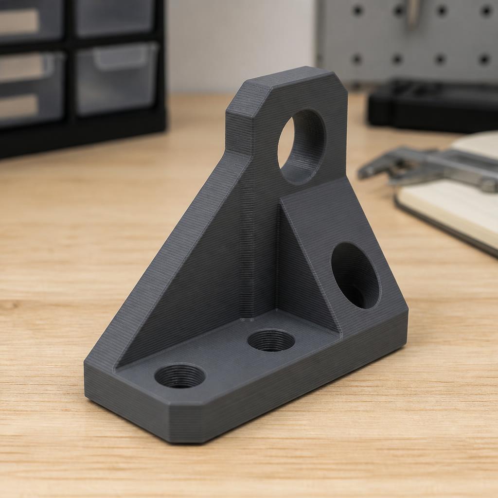
FDM (Fused Deposition Modeling) builds a part layer by layer, bottom up. Every layer needs something underneath it — either a previous layer or a support structure. That is why a model that looks perfect in CAD can, in practice, require lots of supports, have an ugly bottom surface, or fail to print at all. Good Design for Additive Manufacturing (DFAM) solves all of that in CAD, before you ever open the slicer.
The 45-degree rule
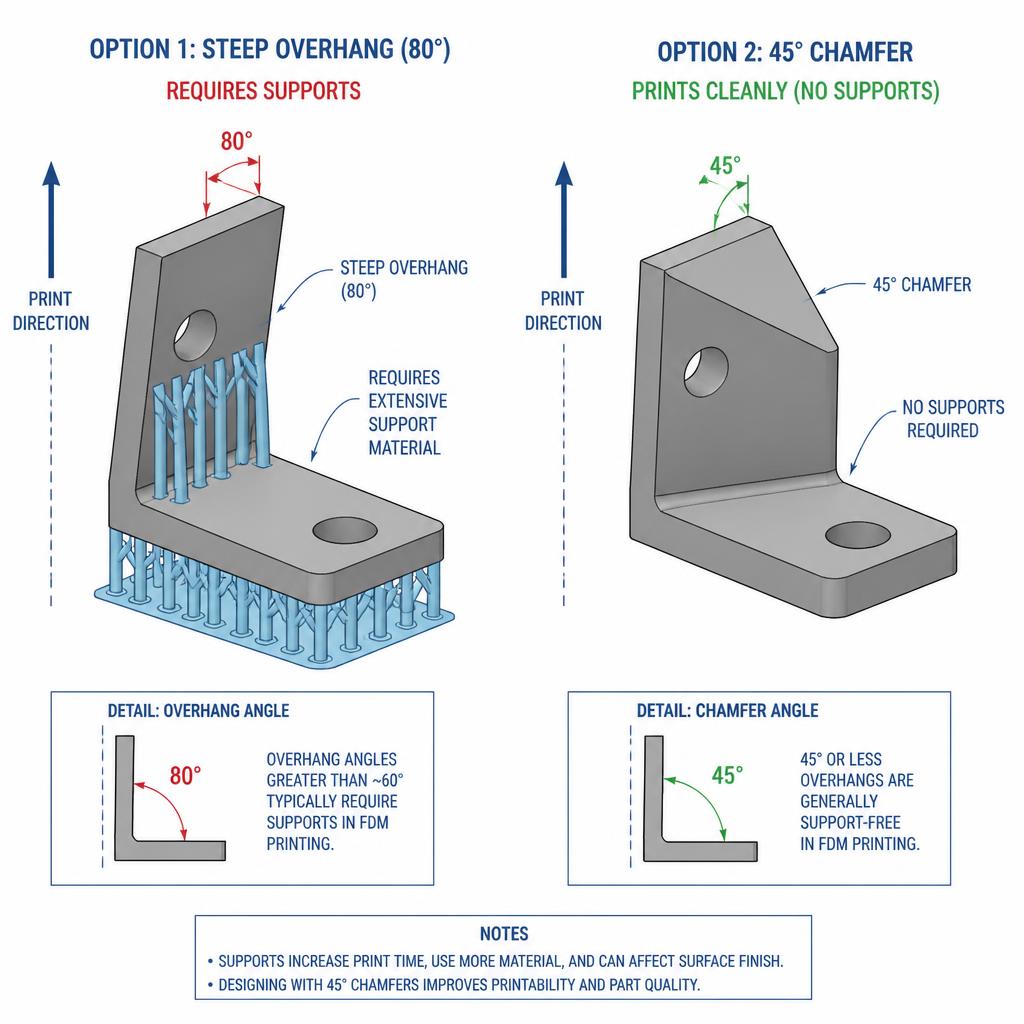
The single most important FDM design rule: overhangs up to about 45° from vertical print cleanly, without supports. Anything steeper (60°, 70°, 80°) usually needs support material, which means longer print time, more filament and a worse surface where the supports touched the part.
Practical uses:
- Chamfer instead of overhang: when an edge has to protrude outward, use a 45° chamfer rather than a rectangular ledge.
- Chamfer instead of a bottom fillet: a downward fillet is really an overhang starting at 90° — a chamfer is always a better choice on the bottom side.
- Tapered transitions: replace abrupt cross-section changes with a 45° taper.
Build plate orientation
Same model, different orientation — completely different result. Before you design, picture how the part will lie on the heated bed.
- Largest flat face down: better adhesion, less warping.
- Fine detail vertical: text, ribs and thin walls come out cleaner when perpendicular to the build plate.
- Strength anisotropy: FDM parts are weakest between layers. Orient the part so the main load runs along the layers, not across them.
Holes, openings and bridges
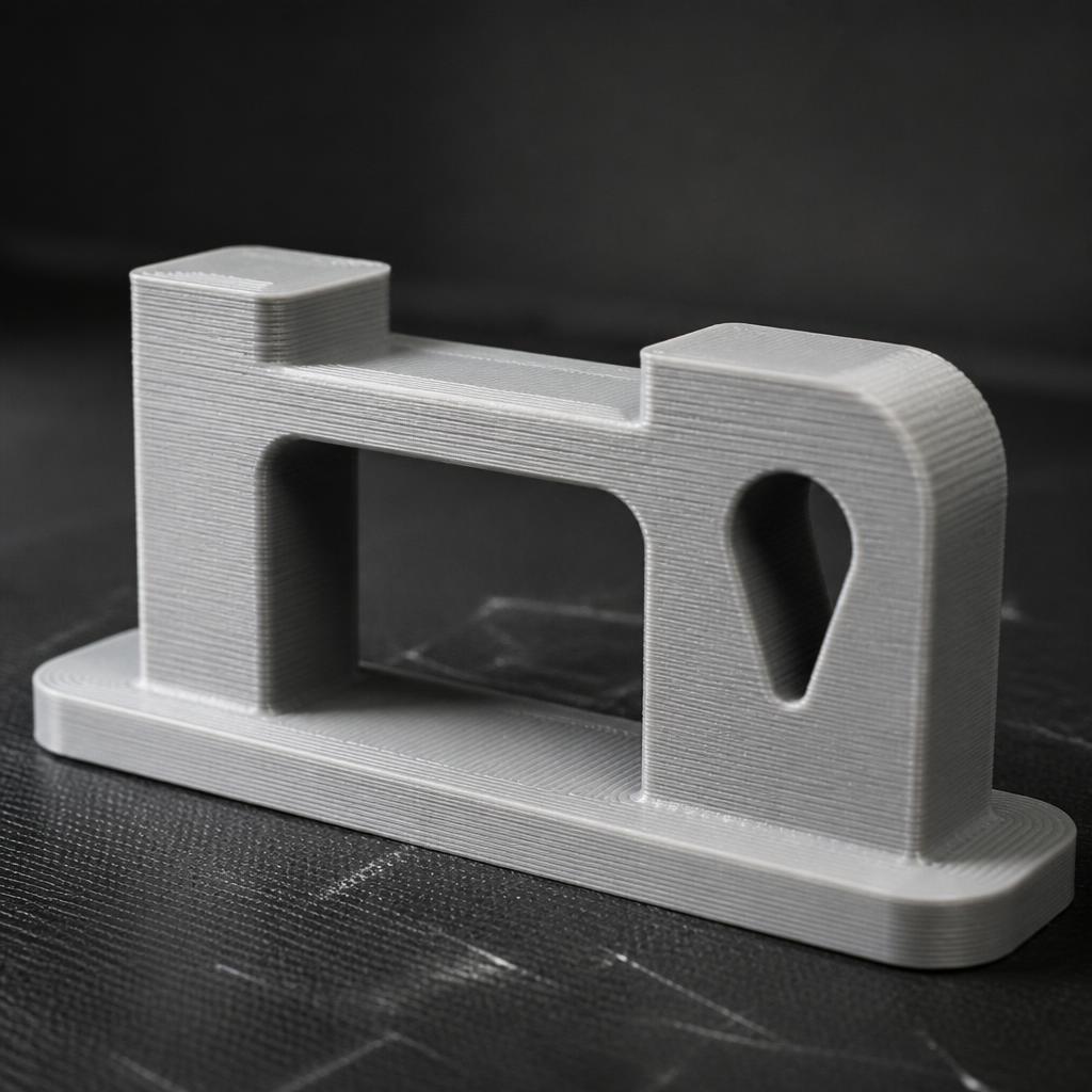
Holes printed parallel to the build plate (horizontal axis) always come out deformed at the top, because the top of the circle is an overhang.
- Teardrop holes: replace the upper half-circle with a 45° triangular tip. The hole keeps its diameter and the print stays clean.
- Bridging: an FDM printer can span an open gap up to roughly 10 mm without supports. Anything longer needs supports or a geometry rework.
- Vertical holes: print great but tend to come out slightly undersized — plan a 0.1–0.3 mm tolerance if a screw or shaft has to pass through.
Manifold and watertight geometry
Slicers love clean models. Non-manifold edges, overlapping faces, inverted normals and internal voids create garbage when the model is sliced.
- Manifold (watertight): every edge is shared by exactly two faces and the model is fully closed.
- No internal cavities: when combining bodies, use Boolean union, not just grouping.
- Check before export: run a non-manifold check in Fusion 360 (Mesh workspace), Blender (3D-Print Toolbox) or Meshmixer before exporting STL/3MF.
- Export resolution: an STL with too many tiny triangles slows the slicer; too few and curves look like polygons. 3MF is the newer, more reliable format.
Wall thickness and minimum detail
- Minimum wall: with a 0.4 mm nozzle, plan for at least 0.8–1.2 mm (2–3 perimeters). Anything thinner will not bond properly.
- Minimum feature: text and ribs below 0.4 mm usually disappear or merge together.
- Prefer embossed over debossed text: raised text is far more legible on FDM than recessed text.
Tolerances for assemblies
FDM is not as precise as CNC. Design clearances in from the start:
- Sliding fit: 0.2–0.3 mm clearance per side.
- Press-fit: 0.05–0.1 mm.
- Screw clearance hole: for an M3 screw, 3.3–3.4 mm.
- Hex nut pockets: add 0.15–0.2 mm to the nut dimension for an easy drop-in.
Fillets on corners
Sharp corners at the bottom of a part are stress concentrators and the first place cracks appear. Add fillets of at least 1–2 mm radius to every outer corner that touches the build plate — it reduces warping and extends part life.
Ribs and lightweighting
A thicker wall is not always stronger. Instead of a solid 5 mm wall, use a 1.6 mm wall with ribs — you get the same stiffness with half the material and print time.
- Rib thickness: 40–60% of the main wall thickness.
- Rib height: up to 3× the rib thickness (any more and it cracks).
- Spacing: at least 4× the rib thickness between ribs.
Advantages of good DFAM
- Shorter print time: no supports, less material, faster turnaround.
- Better surface finish: clean bottoms without support scarring.
- Lower cost: less filament, less post-processing.
- Higher strength: correct orientation puts layers along the load path.
- Repeatability: a good design works across different printers and materials.
Conclusion
Most "problems" in FDM printing are not printer problems — they were created in CAD. When you design with the 45° rule, good orientation, teardrop holes, manifold geometry and realistic tolerances, the printer does what it was built to do instead of compensating for a poor design. If you need help preparing a model for FDM, or want us to take over the full development, get in touch — at 3D4U we handle DFAM consulting and design adjustments every day.