
FDM molds for casting: cement, plastic and resin in a printed tool
How to make a functional mold on an FDM printer — geometry, materials, tolerances and advantages over classic CNC tooling.
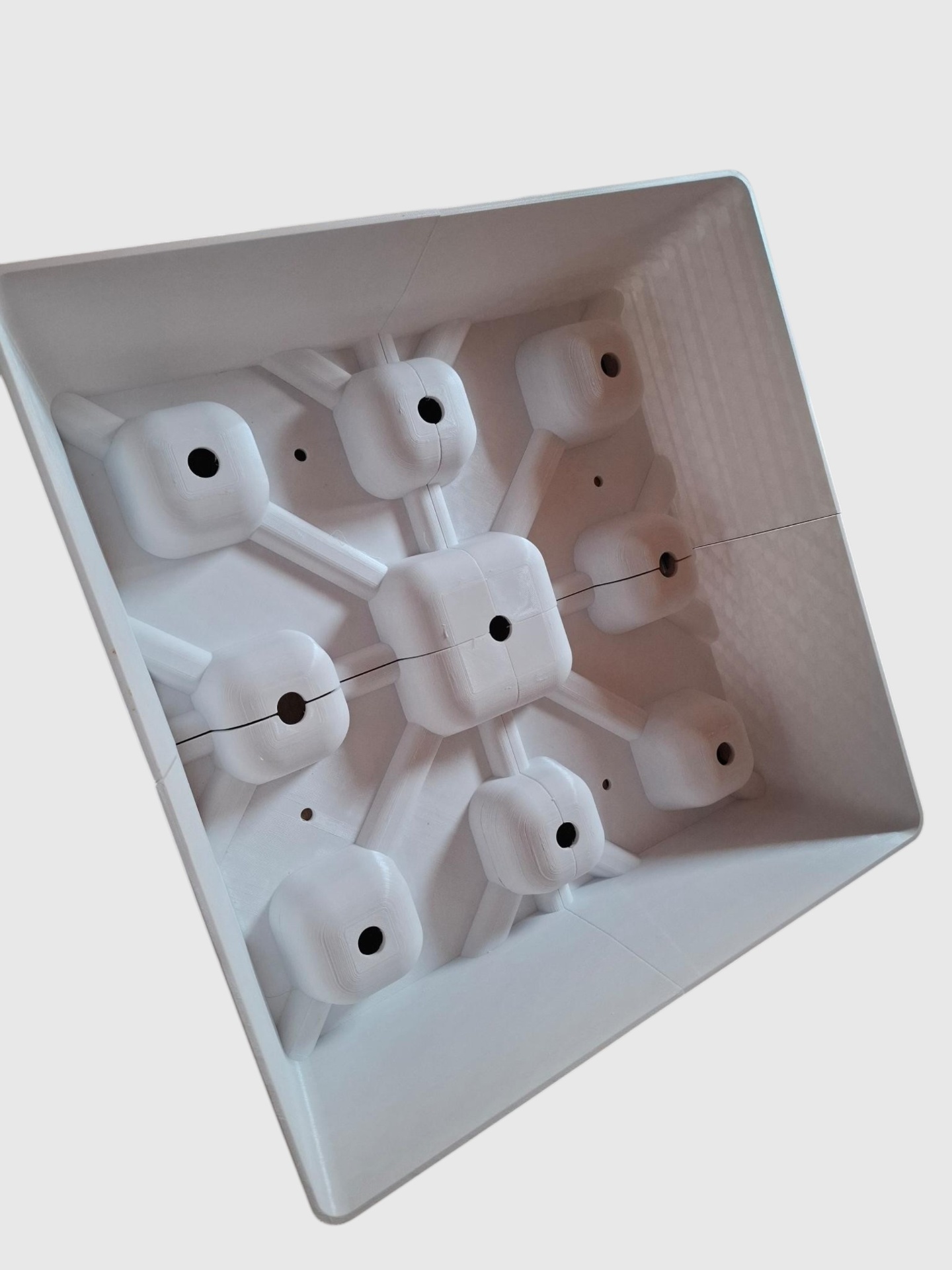
When you need to produce a small batch of castings in cement, plaster, epoxy or low-temperature plastic, machining an aluminum or steel mold on a CNC is often too expensive and too slow. In these scenarios an FDM printer becomes a serious production tool.
The photo shows one such mold — a multi-part FDM tool with a matrix layout for casting eight identical parts in a single pour. You can see the main runners, gate points and the central sprue.
WHY FDM INSTEAD OF A MACHINED TOOL
A CNC-machined aluminum mold with the same geometry means hours of machine time, a dedicated CAM program, fixturing and expensive stock. The FDM version prints overnight from standard filament. For runs of 10 to a few hundred pieces — typical for prototypes, architectural samples, decor and technical parts — this is the difference between a profitable job and a non-starter.
MOLD GEOMETRY AND DESIGN
The mold is split in CAD into segments that are later bolted or clamped together. Key details:
- A parting line with no undercuts so the casting can be released.
- 1–3° draft on all vertical walls.
- A runner system that distributes material evenly to every cavity.
- Vents at the highest points of the cavity to release trapped air.
- Registration features (pin/hole) for accurate alignment of mold halves.
MOLD MATERIALS
Depending on the casting medium:
- Cement, plaster, concrete — PLA or PETG. Water and alkaline media do not damage the polymer short-term, and the mold cleans easily.
- Epoxy resins — PETG or ASA. The exothermic reaction raises the temperature; PLA can deform.
- Low-temperature plastics (melt up to ~100 °C) — ASA, PC-CF or PA-CF for dimensional stability.
- Silicone and polyurethane rubber — any standard FDM material, no chemical interaction.
PROCESS AND TOLERANCES
The mold is printed with 100% infill in the cavity zone and 40–60% in the rest of the body. Wall thickness at least 3–4 mm to withstand casting pressure and any shrinkage.
The cavity surface can be left as it comes off the printer (for rustic cement castings this is even desirable — the layer texture reads as intentional) or smoothed with epoxy, XTC-3D coating, sanding and clear coat.
Achievable tolerances: ±0.2 mm over 100 mm. For most castings that is more than enough.
ADVANTAGES OF FDM MOLDS
- Tool cost 5–20× lower than CNC.
- 12–48 hours to a working mold instead of a week or two.
- Cheap design iteration — change the CAD and print a new revision.
- Complex internal geometry (ribs, thin channels) that CNC struggles with is trivial in FDM.
- The mold is recyclable — regrind to pellets or drop in the sorting bin.
LIMITATIONS
An FDM mold will not survive injection molding of thermoplastic under high pressure and temperature. This is a tool for gravity casting, manual pouring and low-pressure processes. Real injection molding still needs aluminum or steel.
WHEN AN FDM MOLD IS THE RIGHT CHOICE
- Small and medium runs (10–500 pieces).
- Prototype castings before investing in a steel tool.
- Architectural and design samples — concrete, plaster, soap, candles.
- Spare parts no longer in production.
If you need a mold for casting or replicating a part — send us the CAD or a photo, and we will assess whether FDM is the optimal solution or a hybrid with CNC is required.